Build
Before getting started
Just a note for those contemplating ANY kind of project - find and join online community groups and forums! The wealth of expertise and knowledge out there is incredible and I would not have undertaken this project without the support and encouragement of other moped/ebike builders and hobbyists. For those of you who have commented on my project and shared your expertise through one of these forums, I thank you!

Where to begin?
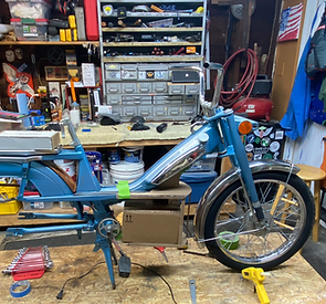
After dismantling the kayak strongback form from my homemade motorcycle stand, I proudly perched the Mobylette on what would be her pedestal for the next few months. Note the condition of that seat and the duct-taped taillight. Yep, no extra cost for those items.
With most projects, I have a general budget in mind, but as those of you involved in these types of projects know, that quickly goes out the window when you start creating the wishlist of components, add-ons, and must-haves. Of course, wishlists change as projects evolve, but to keep track of everything, including vendors, ship dates, costs, etc. I always create a Google spreadsheet.
Here's my "current"
Spreadsheet for the 50ev Conversion
I always start with the list to keep track of expenses, but more importantly, I like to refer back to my lists if I ever do similar projects.
Another thing I do before starting a project is to create a folder under my Google Drive account where I store photos, videos, manuals, spreadsheets, sketches and anything else related to the project. It's fun to look back on previous projects and it serves as my digital repository that I can share with others who are interested.
Here's a link to my
Step 1: Design
The look of the bike was important to me, so I first started sketching designs, thinking loosely about where components would go. At first, I didn't know the dimensions of controllers and motors. I didn't even know if I wanted a mid-drive or hub-drive motor (I barely knew what options existed). Most importantly, though, I didn't want my project to look like a cobbled mess when finished. I made a lot of sketches and I focused on the battery housing since this was going to be the area requiring the most modification to the existing frame. I used the free tool Sketchup to design my final version of the battery housing (center sketch below).


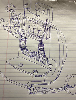
I've always liked art deco styling and even though my Motobecane was built decades beyond the art deco era of the 20s and 30s, I wanted to add classy elements to the design of the battery housing that wouldn't look too out of place. While researching Art Deco, short for Arts Décoratifs, I found out that the style originated in France, so it seemed appropriate to incorporate elements into my French moped.


After doing a considerable amount of online research (Endless Sphere was invaluable source for DIY ebike information), I decided to go with the hub motor configuration since I needed more space for the battery, and adding a mid-drive motor just wouldn't be feasible unless I relocated the battery to the back rack. Since the battery is the heaviest part of the bike, I wanted to position it low and center for ride stability. I'm glad I did because it turned out to be a really stable and smooth ride.
I ordered the 3000W, 72V hub motor, controller, display (UKC1 color), controls, and spokes to fit the orignal 26" Moby rims from NBPower. Shipping from China took about three weeks and I received excellent communication, including invoice and tracking numbers from the vendor through WhatsApp. I purchased the 72 volt, 30ah battery from eBay.

I researched a number of hub motor manufacturers and finally landed on NBPower, manufactured in China and sold through Amazon (I purchased directly from them using PayPal). I'd read the reviews and saw that buyers had nothing but good things to say about the hardware and support. Despite the language barrier, I found NBPower's support to be excellent and responsive and we communicated mostly through WhatsApp. Videos and screenshots sent through the app resolved any language barriers and I would not have needed their support at all except that I accidentally fried the color display when I shorted two wires during installation. They sent me another one at no charge. Lesson learned - keep your workspace clean and positive and negative contacts isolated! I have to say, The technician's use of emoticons during our chats was not only funny, but reduced some of the stress that I was experiencing when things weren't going as planned.
Step 2: Fabrication
With the design of the battery housing roughly sketched out and components for the build on order, I turned my attention to the tools and materials I would need to fabricate the compartment.
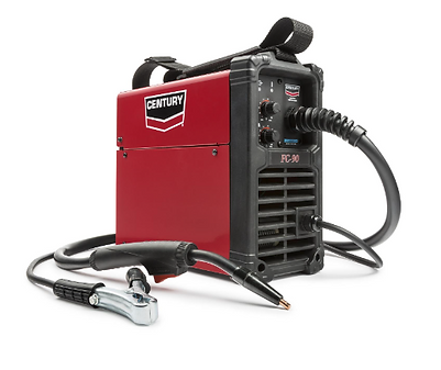
I had never welded anything in my life, but I knew that welding would be required to fabricate the housing frame and I was eager to learn something new. I watched countless YouTube videos to educate myself on welding equipment and techniques and I was prepared to buy an inexpensive flux-core welder when my next-door neighbor (and brother-in-law), Mark, offered to loan me his for the project. He also provided wire, magnets, welding helmet, and a few tips and pointers which were very helpful. Thanks Mark!
I'm still not a great welder, but I learned a lot on the job, and I ended the project with greater skill than when I started — one of the many reasons I enjoy building projects like these. For those reading who would like to get started welding, I used the Century 120-Volt, 80-Amp, flux-cored wire feed welder, which you can pick it up for a little over $200. It was perfect for this project and a good machine to learn on.


Other tools and supplies that I used on this project: Dremel with cutting and sanding discs, grinder, chop saw, utility knife, drill, router, pop rivet gun, CA glue, Sikaflex-221 adhesive, Loctite, matte board/cardboard (for templating), velcro, screw-posts (to connect aluminum bar stock to ACM panels), rattle can paint and clearcoat, and, of course, JB Weld.
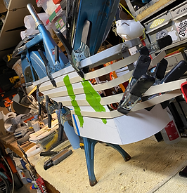
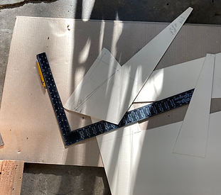
A word about templates: For almost all projects that require fabrication and proper sizing of components, I use templates. It's not a new or novel concept, but it saves me a ton of time and material when I can build stuff out of cheap materials before I use expensive supplies. For this project, I used templates to create actual-size mock-ups of components (controller, battery, step-down converter) before they arrived in the mail. This allowed me to size the battery housing appropriately before welding. I also created templates for the side panels to adjust my design for visual appeal and to check proper fitment. I used corrugated cardboard and damaged matte board that I picked up cheaply from the frame shop down the street for my templates and I cut and re-cut boards until the design looked and fit right. I then used the templates to trace my outlines onto the final materials.
I initially thought that I would weld sheet metal to the metal battery housing frame, but sheet metal is tricky to cut and form, and it's easy to burn holes through when you're just learning to weld. After some web surfing, I came across a product called ACM (Aluminum Composite Material), which is basically polystyrene plastic sandwiched between two thin pieces of aluminum. It's used in the sign-making industry, but it is also used for sheathing small camper trailers. This stuff is tough, easy to cut, easy to mill, easy to glue (with CA glue and JB weld), and provides a nice paintable surface. All of the panels in my project were made of ACM and I'm really happy with the results. For curved ACM surfaces, I routed 1/8" parallel channels on the reverse side of the exposed surface. This allowed me to roll the surface without breaking the thin aluminum that the ACM is made with. Once the surface was rolled into the desired curve (the front of the battery housing), I would run a bead of CA glue into the 1/8" channels on the reverse (hidden) side to fix the shape in place. After sanding over the top of the CA glue, I would spread JB weld to further solidify the joint.

After cutting and forming the ACM panels, I laid a thin bead of Sikaflex 221 sealant/adhesive down on the frame where the panels would be attached and I used pop rivets to fix them in place. I wanted to be able to easily remove the battery, so the left side panel is hinged at the front. A keyed lock was installed at the rear of the panel to discourage easy removal of the battery. The lock catches on the lip of the L-channel lower frame.
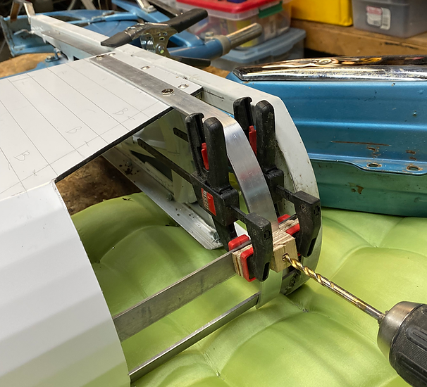
1" aluminum bar stock was cut on the table saw and gently formed in my vise into gentle curves that slope around the front. I used a wooden jig to pre-drill holes in the strip. After painting the panels, I attached the strips with Chicago screw posts (see my materials list for these). When I worked in the print industry, we used these screw posts to bind thick sets of blue prints and they worked perfectly to attach the decorative trim pieces to the ACM. Best of all, I could dry-fit the trim before painting. The posts work like removable rivets, and to ensure they don't rattle loose with road vibration, I used a dab of Loctite on each one during final installation.


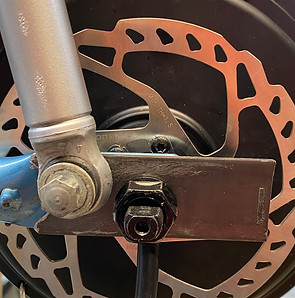
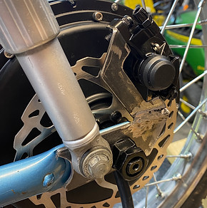
The last bit of fabrication before reassembly was to make torque brackets and mount for the rear disc brake caliper. For those new to ebikes, they are torque-y little fellas, and the 3000W hub motor I used will create 70 foot-pounds of torque - enough to strip out rear wheel dropouts of lighter bikes and mopeds if you full-twist the throttle from stop. Most ebike hub motors require torque brackets (extra steel to prevent tearout), and even though my hub motor came with brackets, they would not properly fit the Motobecane's swing arm. For the left-side bracket, I decided to incorporate the caliper mount and the photos below show the final bracket before painting. The right side bracket is a mirror image of the left, minus the brake caliper mount. You'll notice that the shock bolts also pass through the brackets which, along with hub spindle bolts, fixes them in place. The brackets were made from 1/8" steel bar.

Step 3: Electrics and Cabling
Wiring the kit together was fairly straightforward. The hub motor has three phase wires that are color coded to meet up with the corresponding wires from the controller. Connectors from the controller (mounted below the battery housing) match up with controls: brake levers, display, PAS (pedal assist) system and output to the 72 volt to 12 volt step down converter (for lights and horn). Phase and battery wires connect through a yellow junction box, provided with the kit. Other items I ordered to complete the electrical system installation included: 50 amp circuit breaker, 10 amp in-line fuse, 72v to 12v converter, terminal block for wiring inside the headlight shell, new horn, front turn signals, flasher relay, combination light/turn signal/horn control switch, and new rear tail light assembly. I kept the original headlight but bypassed the original light switch on top of the headlight.
To make electrical connections easier, I fabricated a removable "junction box" out of ACM. This allowed me to make phase wire connections and route other wire connectors from the controller through what would be the back side of the battery housing before installing it on the bike. I was happy with this design feature since I could make most of the connections on the bench.
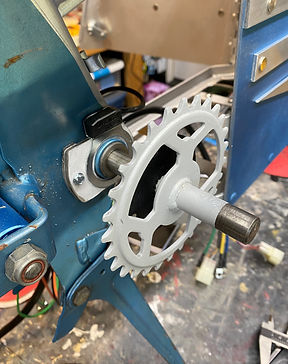
At first, I wasn't sure if I was going to be able to install the pedal assist system since there wasn't enough room for the sensor and magnetized rotor on the left-side crank spindle due to the fact that wiring from the controller enters the bottom side of the battery housing on that side. The right side had room, but it became clear that I would have to fabricate a custom bracket for the sensor since it was designed for a standard bicycle bottom bracket. Photos below show the bracket mount that was made quickly and easily with ACM.


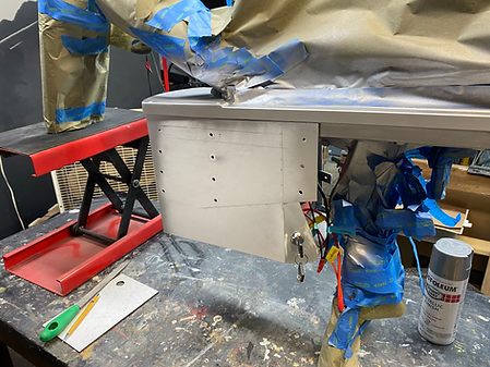
I mounted the 72-volt to 12-volt step-down converter to ACM and used double-sided velcro to mount it to the interior roof of the battery housing. After the battery and wiring were installed, there wasn't a lot of room for the battery to move around, but just to make sure everything was snug, I cut and formed high-density foam to fill the void at the front and top of the battery. These foam blocks can easily be removed with the battery. I've also seen velcro straps used on other projects to keep the battery in place.
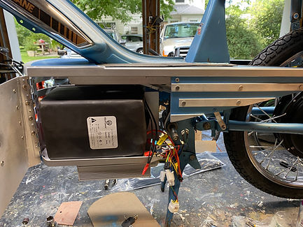
NBPower told me that I didn't need to install a fuse between the battery and the controller, but I wasn't very comfortable with that, so I found and installed a 50 amp circuit breaker switch (yellow buttons to the right of the battery compartment in the photo). I'm glad I made this decision. Not only does it provide some peace of mind with power surges, it also acts as a hidden ignition switch behind the left-side panel. To start-up the bike, I click the yellow switch on before powering up the display. To turn off, I reverse the process. This also ensures that I don't drain the battery if I accidentally leave the lights on.

Step 4: Painting and Finishes
Coming soon...